PlyNex
PlyNex
Developing efficient 3D modelling and optimisation methods
to support faster, more reliable composite laminate design.
The Mesh Bottleneck in Composite Laminates
Modern composite structures are becoming larger, lighter, and more ambitious. Wind turbine blades now reach massive scales, with load-carrying components such as spar caps and shear webs built from thin stacks of composite plies. Each ply may be only a small part of the structure, but the stresses that matter most—interlaminar stresses, free-edge effects, and delamination-driving traction fields—often live exactly at the interfaces between those plies. The poster frames this challenge in the context of very large wind turbine blades and thin stacked composite laminate substructures.

That is where conventional continuous Galerkin finite element modelling becomes difficult. In standard CG-FEM, neighbouring elements share nodes, so displacement continuity is enforced directly through the mesh. For thin laminates, this often forces analysts to use low-aspect-ratio elements and heavy through-thickness refinement across large in-plane spans. The result is a model that may be accurate, but also large, slow, and difficult to use inside design studies, optimisation loops, or repeated certification-style analyses. The parent paper states the same core issue: conventional 3D finite element models based on low-aspect-ratio elements can become impractically large when thin plies must be resolved over wide in-plane dimensions.
For engineers, this creates a familiar compromise: use a reduced-order model and risk missing the local 3D physics, or build a full 3D model and pay the price in meshing effort, degrees of freedom, runtime, and post-processing complexity. Our work targets that compromise directly.
DG-FEM: Continuity, Reimagined
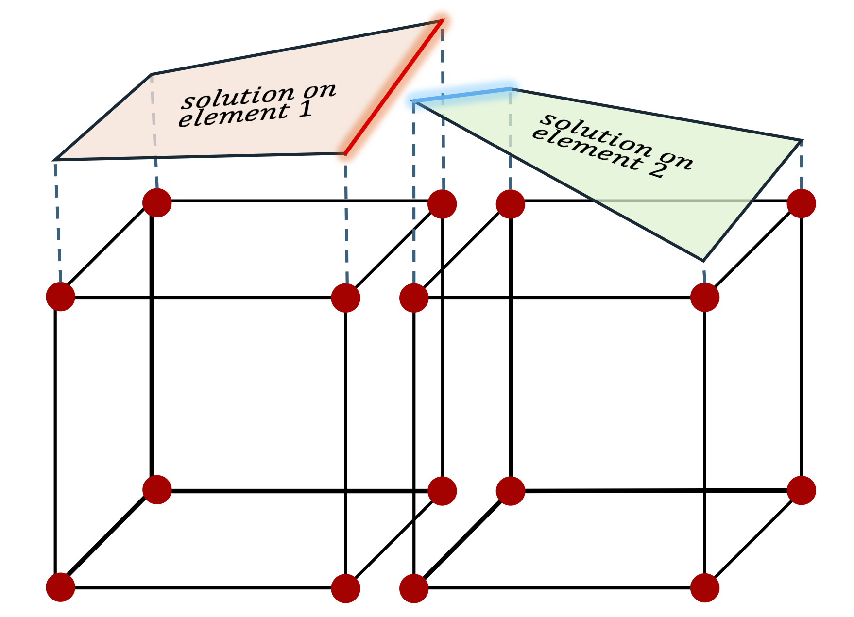
Discontinuous Galerkin finite element methods take a different view of the mesh. Instead of forcing neighbouring elements to share the same displacement values at common nodes, DG-FEM allows each element to carry its own local solution. Continuity and traction transfer are then imposed weakly through numerical fluxes and penalty terms at the interfaces. In simple terms, CG-FEM builds continuity into the mesh; DG-FEM enforces it through the formulation. The parent paper describes this explicitly: DG approximation spaces do not enforce displacement continuity across element interfaces, while interelement continuity and traction transfer are enforced through consistent numerical fluxes and jump-penalty terms.
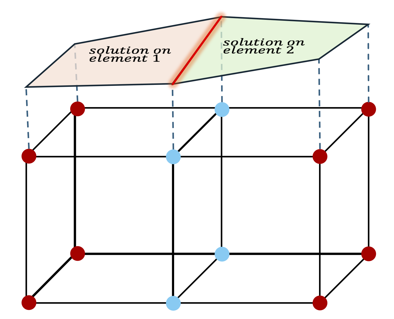
This distinction is powerful for composite laminates. Laminates are naturally anisotropic, layered, and direction-dependent; the strongest gradients are not everywhere, but around free edges, ply interfaces, and local stress-transfer zones. DG-FEM makes it possible to use stretched, high-aspect-ratio hexahedral elements that follow the physics of the laminate rather than forcing the whole structure into a uniformly dense mesh.
For composite engineers, this means the mesh can finally behave more like the material: thin through the thickness, extended in-plane, refined where stress concentrations develop, and coarse where the structural response is smooth.
A 3D DG Solver Built for Laminates
We have developed a three-dimensional discontinuous Galerkin finite element solver designed specifically for high-performance composite laminate analysis. The solver uses a symmetric interior penalty DG formulation for orthotropic plies, with material stiffness transformed according to fibre orientation and interface behaviour handled through DG flux and penalty terms. The paper positions this formulation as a framework for orthotropic laminates on stretched hexahedral meshes, allowing refinement to be aligned with stress concentrations while keeping the global structural mesh coarse.

The workflow is built around the real needs of laminate modelling: define the laminate stack, assign material properties and fibre angles, generate a targeted high-aspect-ratio mesh, solve the full 3D elasticity problem, and post-process the ply-level and interlaminar stress fields. Instead of spending computational effort everywhere, the solver concentrates resolution at the locations where the laminate is most vulnerable—free edges, ply interfaces, and stress-evaluation paths—while avoiding unnecessary refinement in regions where the stress field is smooth.
This is not a shortcut around 3D analysis. It is a more efficient way to perform it. The result is a compact, mechanically targeted model that can recover the local stress information required for understanding free-edge effects, interface traction transfer, and delamination-prone regions in composite laminates.
30× Faster Laminate Simulation
The efficiency gain is the clearest signal that this approach can change how composite laminates are analysed. In the cross-ply free-edge benchmark, the DG-FEM model used a graded 4 × 4 × 4 hexahedral mesh, only 64 elements, and 12,288 degrees of freedom. The hierarchical conforming FEM reference model used 9,428 elements and 134,655 degrees of freedom. The DG-FEM analysis completed in 4.82 seconds, compared with 154.02 seconds reported for the reference benchmark.

For an analyst, this is more than a faster run. It means more laminate configurations can be tested, more fibre-angle choices can be explored, and more design iterations can be completed before cost or schedule becomes the limiting factor. For a company developing wind turbine blades, aerospace structures, marine composites, or other layered lightweight components, that speed can turn high-fidelity 3D stress analysis from an occasional verification step into a practical design tool.
The angle-ply benchmark further supports the scalability of the workflow: the DG-FEM model used 24,576 DOFs on an 8 × 8 × 4 hexahedral mesh and completed in 6.39 seconds, while still matching the reference stress profiles closely.
Stress Accuracy Where Failure Begins
Speed only matters if the critical stresses survive the simplification. In composite laminates, the most important information is often not the global deformation, but the local interlaminar stress field—especially near free edges and ply interfaces, where delamination can initiate.
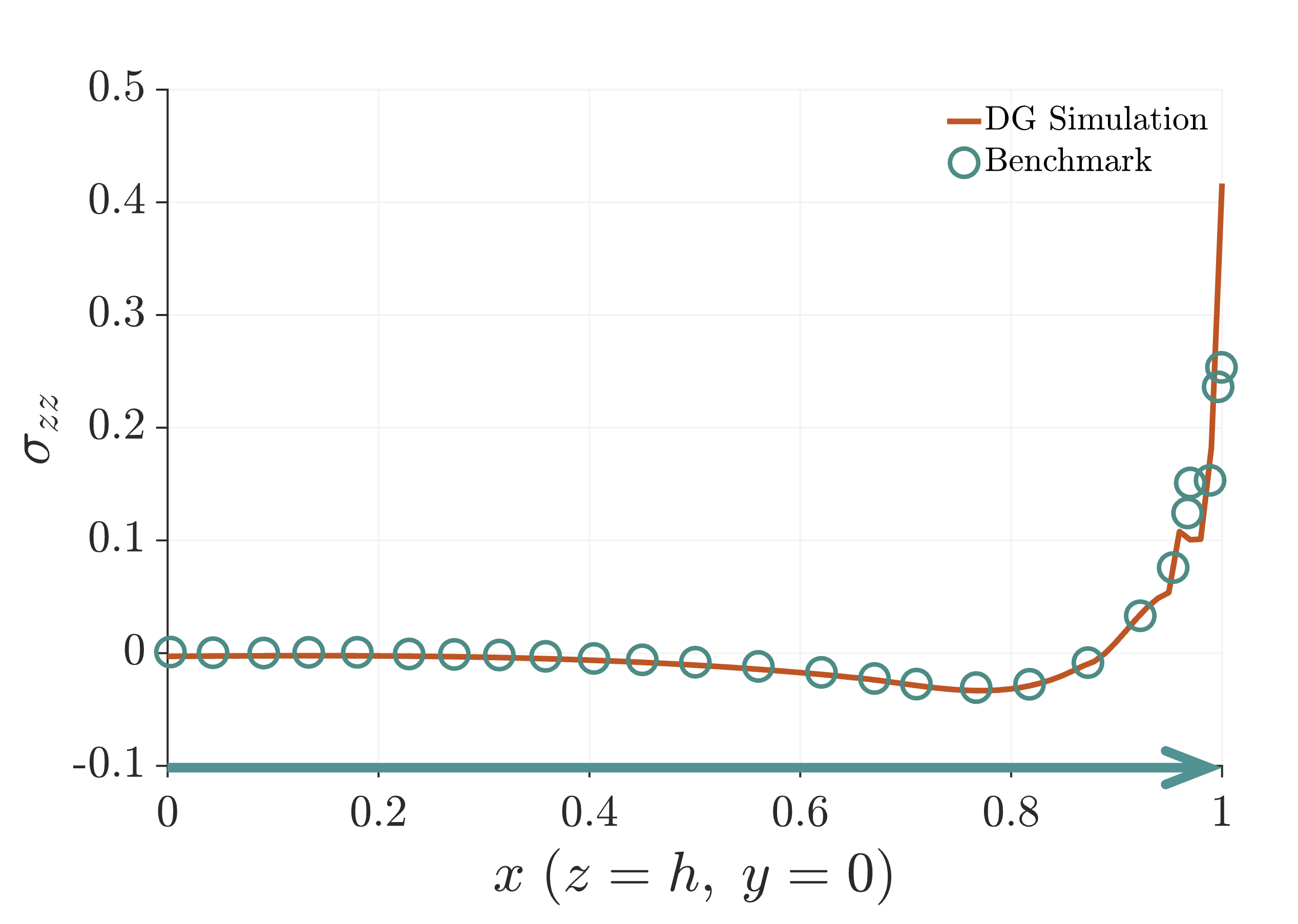
The benchmark stress plots show that the DG-FEM solver reproduces the key stress behaviour with excellent agreement against established hierarchical conforming FEM data. In the cross-ply benchmark, the paper reports that the DG-FEM results capture the characteristic free-edge stress concentrations, including the local peak in the out-of-plane normal stress and the sharp sign reversal in interlaminar shear stress. Agreement with the reference data is described as excellent in both amplitude and spatial distribution, despite the coarse mesh and extreme element aspect ratios.
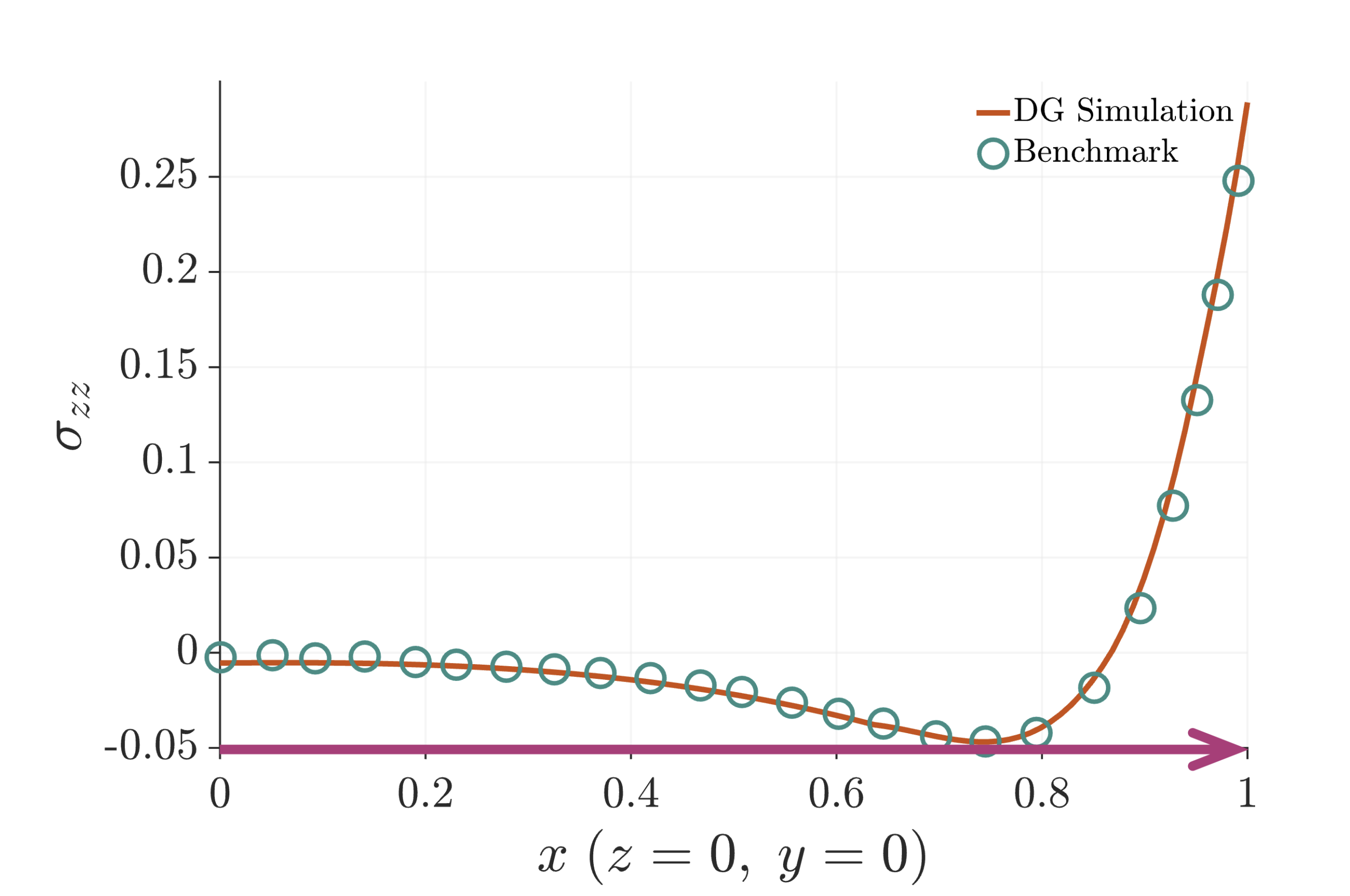

That combination—fast computation with faithful interlaminar stress recovery—is the core value of the project. It allows engineers to focus on the stress features that govern laminate reliability, rather than fighting the mesh required to see them.
From Simulation to Laminate Design Intelligence
This project is moving beyond faster analysis toward intelligent laminate design. The next step is to connect the ultra-fast 3D DG solver with optimisation frameworks that can explore material choices, ply sequencing, and fibre angles across the laminate stack. The poster shows this future direction clearly: a DG solver coupled with a material library, fibre-angle definitions, and an optimisation algorithm to automatically optimise the material and fibre angle for every individual ply.
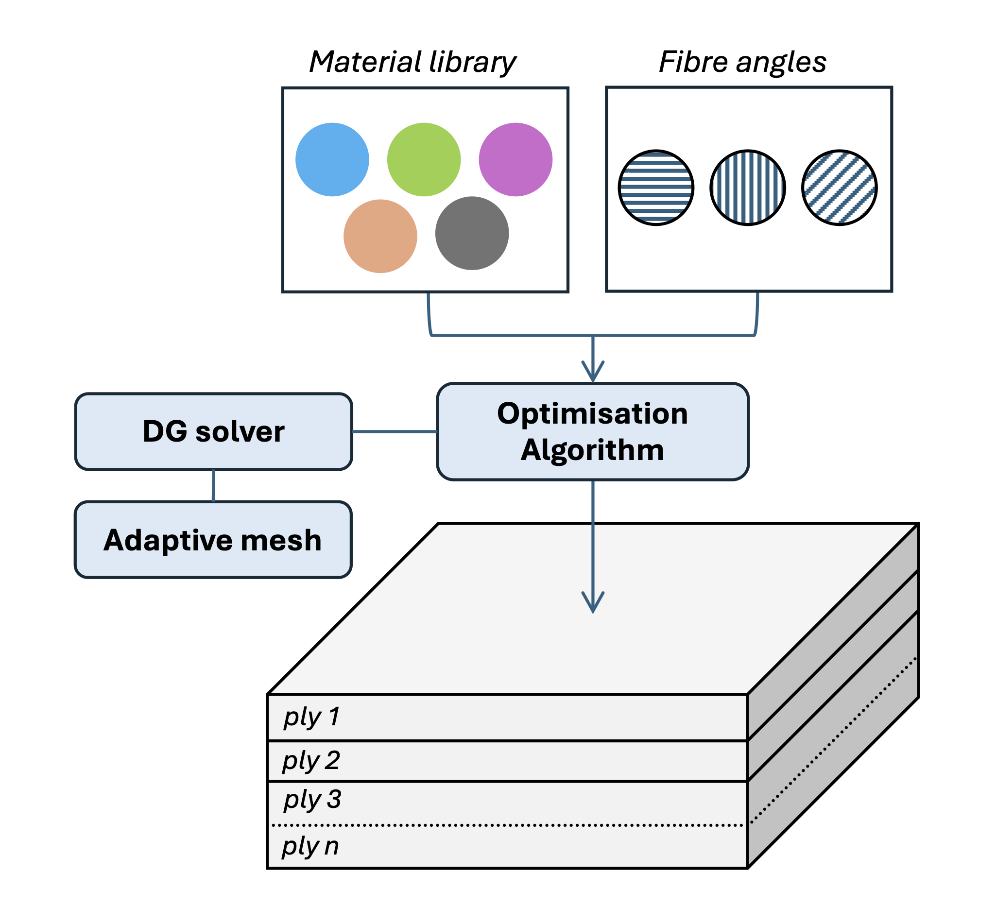
The long-term vision is a simulation framework that does more than validate a design after it has already been chosen. It should help generate better designs from the beginning: lighter laminates, safer interfaces, smarter stacking sequences, and faster iteration cycles. For industries working at the edge of structural performance—wind energy, aerospace, advanced manufacturing, marine composites, and high-performance lightweight structures—this creates a route toward 3D stress-informed optimisation at a cost that can fit real engineering workflows.